Description
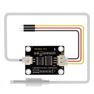
Analog TDS Sensor Module V1.0 (Gravity-style) — Waterproof Probe, 5V, Analog Output
Meet the Analog TDS Sensor Module V1.0—a compact, stable, and calibration-friendly board for measuring Total Dissolved Solids (TDS) and electrical conductivity (EC) of water. This version pairs a waterproof probe with a precision signal-conditioning board that uses a low-noise op-amp and an onboard oscillator to drive the sensing electrodes with an AC-like excitation—reducing electrode polarization and extending probe life. Read the analog voltage (AO) with your MCU, map it to ppm TDS or mS/cm EC, and you’re ready to monitor RO/DI systems, aquariums, hydroponics, or lab samples.
Highlights
- Simple 3-wire host interface: VCC, GND, AO to any 5V microcontroller (Arduino, ESP32 5V-tolerant via divider, etc.).
- Linear, low-noise output: Precision conditioning around a LMV324-class op-amp for stable readings with averaging.
- AC excitation driver: CD4060-class oscillator helps minimize electrode polarization and measurement drift.
- Waterproof probe: Durable stainless electrodes with long lead for immersion measurements.
- Trim for range: Onboard trimmer (where present) to fine-tune scaling for your container and target ppm.
- Calibratable to ppm or EC: Quick 1- or 2-point calibration using standard solutions (e.g., 1413 μS/cm).
- Compact PCB: About 42 × 32 mm with four M3 mounting holes; JST-style headers for neat wiring.
- Reverse-polarity hints & silkscreen: Clear “A + –” marking near the host header, probe header keyed.
What you can build
- Aquarium & reef monitoring (ATO/RODI quality, dosing checks)
- Hydroponics nutrient tracking alongside pH & temperature
- RO/DI output quality verification (e.g., alarm when TDS rises)
- Education & lab experiments on conductivity/TDS
- Light industrial water checks (non-hazardous fluids)
How it works
- Excitation: The board drives the probe with a low-amplitude AC-like signal derived from a CD4060 oscillator stage.
- Sensing: Conductivity of the solution changes the probe impedance; the analog front-end (LMV324 op-amp family) converts it to a voltage.
- Reading: Your controller samples AO and converts it to EC (μS/cm) and then TDS (ppm) using a temperature-compensated formula and your calibration constants.
Mechanical overview
- PCB size: ~42 mm × 32 mm (1.65″ × 1.26″)
- Mounting: 4 × corner holes (≈M3)
- Connectors: Right 3-pin host header marked A + –; left JST for probe (waterproof).
- Finish: Black PCB, white silkscreen “TDS Meter V1.0”.
Pinout & wiring
Host side (3-pin header, marked near “A + –”):
- A (AO) — Analog output to MCU ADC
- + (VCC) — 5 V supply
- – (GND) — Ground
Probe side (JST header):
- Probe + / Probe – — Differential electrodes (most cables: 2 conductors; third pin unconnected on some boards)
Typical MCU wiring
- AO → Arduino A0 (or to ESP32 ADC with proper scaling/reference)
- VCC → 5 V, GND → GND
- Optional NTC/TEMP input: add your own sensor (DS18B20/NTC) for compensation in code.
Quick start (Arduino-style)
- Power at 5 V.
- Immerse the probe in your sample; avoid bubbles or touching container walls.
- Rinse between samples with DI water.
- Take multiple ADC readings (e.g., average 30–50).
- Apply temperature compensation (β ≈ 2%/°C for EC; adjust as needed).
- Convert EC→TDS: TDS(ppm) ≈ k × EC(μS/cm). Common k = 0.5 (calibrate to your standard).
Calibration (recommended)
- Prepare: 0 ppm proxy (fresh DI or distilled) and one standard (e.g., 1413 μS/cm) or two standards (e.g., 1413 & 2764 μS/cm).
- Record ADC in each standard at a known temperature.
- Fit linear mapping ADC → EC; store slope & offset in code.
- Re-check monthly; clean probe with mild rinse if drift appears.
Best practices
- Keep liquid temperature stable; compensate in firmware.
- Avoid bubbles and agitation while reading.
- Don’t scrape or sand electrodes; rinse instead.
- Do not exceed low-voltage aqueous solutions; avoid solvents/acids/alkalis.


Reviews
There are no reviews yet.